This is my second technical post on using hemispherical photography for light estimates. My previous post considered the rationale behind hemispherical photography estimation methods. This post will cover hardware, specifically:
- Lens
- Camera
- Stabilizer
One of the reasons for the lack of standardization in hemispherical photo techniques is the rapid pace of improvements in camera technology. In the earliest days of hemispherical canopy photos, researchers shot on film, developed the images, and scanned them into digital images for processing (Rich 1989). Now that digital camera sensors have improved, we can skip the development and scanning steps, and the accuracy of techniques have also increased. However, substantial bias can creep into light analyses if the data are captured without a solid understanding of hardware (covered in this post) and settings (covered in the next post).
At the most basic level, hemispherical photography requires just three pieces of hardware: a camera, a lens, and something stable to mount it to.
Lens:
Arguably, the lens is the most critical piece of equipment, because without a true hemispherical lens with an appropriate projection, all photos, regardless of the camera, will be biased.
Fisheye versus hemispherical:
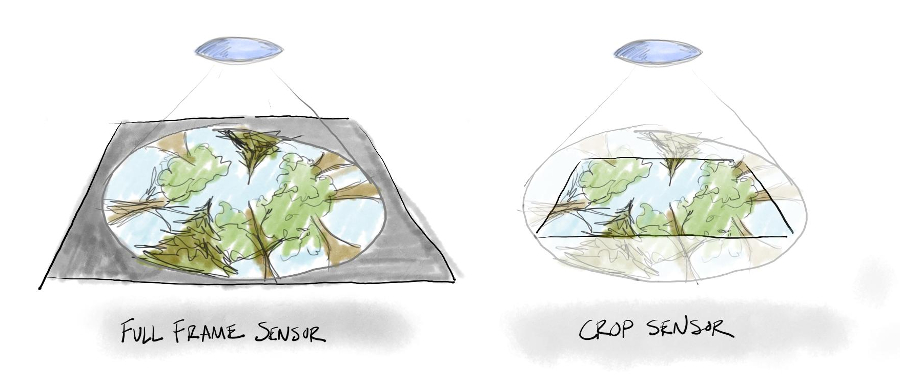
Hemispherical lenses are relatively rare in the camera world. In your hunt for the perfect lens, you will more likely come across many variants of fisheye lenses, which are more commonly used in traditional photography. Hemispherical and fisheye lenses are similar in that they capture a wide-angle of view and project it down onto the flat and rectangular camera sensor. In fact, both types of lenses can be built with the same glass. The main difference is that hemispherical lenses focus a circular image ON the sensor, whereas fisheye lenses project a circle AROUND the sensor, so that the resulting image is rectangular (see figure below).
Hemispherical lenses are extremely uncommon. Lens manufacturers produce these primarily for research purposes. Fisheye lenses, on the other hand, are common—almost every manufacturer makes a few focal lengths.
So how do you find a true hemi-lens? The most certain method is to buy a tried and true model (I use the Sigma 4.5mm f2.8). Otherwise, you can try to find a lens that captures 180 degree angle of view and results in a circle within the photo frame. However, be aware that not all hemispherical lenses are created equal. Different lenses produce different angular distortion, and this distortion can radically alter light estimates.
Lens projection:
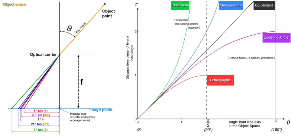
The ideal lens for hemispherical canopy measurements will retain the same area over any viewing angle (i.e. “equal solid angle” in Herbert 1987; or “equisolid” in Fleck 1994).
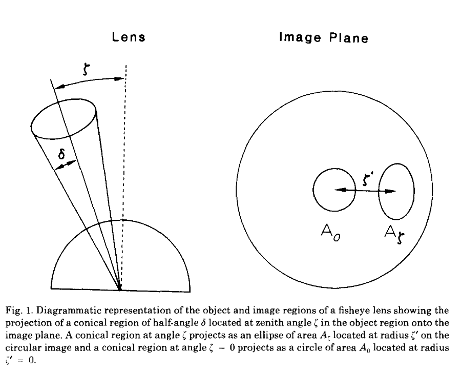
In other words, an object should take up the same number of pixels if it is in the center of the frame (zenith angle = 0) or the very edge of the frame (zenith angle = 90), although the shape may be distorted. But, this is not the case for most lenses which look like a funhouse mirror depending on the zenith angle of view. The difference originates in the intended application of the lens. Most traditional photographers prefer fidelity of shape over fidelity of area. For instance, landscape photographers don’t care if a field of flowers maintains constant shape across an image, but they certainly want all of the flowers to retain a flower-like shape. For this reason, most common fisheye lenses employ another common radial projection called “equidistant”, in which each pixel represent the same angular value at all zenith angles and maintains shape at all viewing angles (see the difference in the image below). (Fleck (1994) does a great job explaining the math behind angle projections, why some are better for different applications, and why some of them look so strange.)
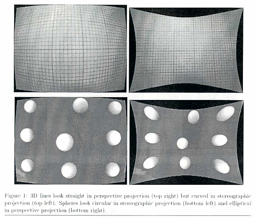
Michael Thoby’s post is one of the most comprehensive and easy-to-follow explanations I’ve found to explain the many radial distortions lenses can accommodate. He even has some neat, interactive example of various projections in this post.
Calibrating lens projections:
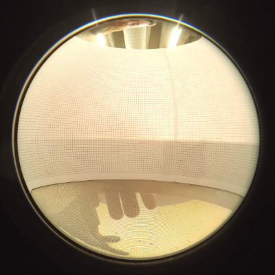
Not all lens manufacturers will explicitly indicate which radial distortion they use. Nevertheless, you can easily calculate the projection of any hemispherical lens empirically with a couple sheets of gridpaper and a round frame (I used a sieve from the soil-microbe lab). Simply affix the grid sheets to the inside rim of the frame, place the camera inside with the edges of the lens lined up along the chord across the diameter, then snap a shot (see image below).
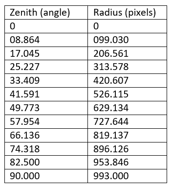
In ImageJ (or similar program), measure the pixel count across the diameter of the image frame. Next, count the number of cells across the diameter of the photo. Dividing the number of cells across the diameter by 18 (or 36) will tell you how many cells represent each 10 (or 5) degree angle of view. Now, starting at the center of the image (i.e. the pixel count across the diameter divided by 2) and moving outward, count the cells (which each represent a known degree angle) and measure the total pixels. Continue doing this from the center (zenith angle = 0) out to the outer edge of the image (zenith angle = 90).
For example, here are the empirically derived projection estimates for the GoPro/Lensbaby180+ lens setup I tested:
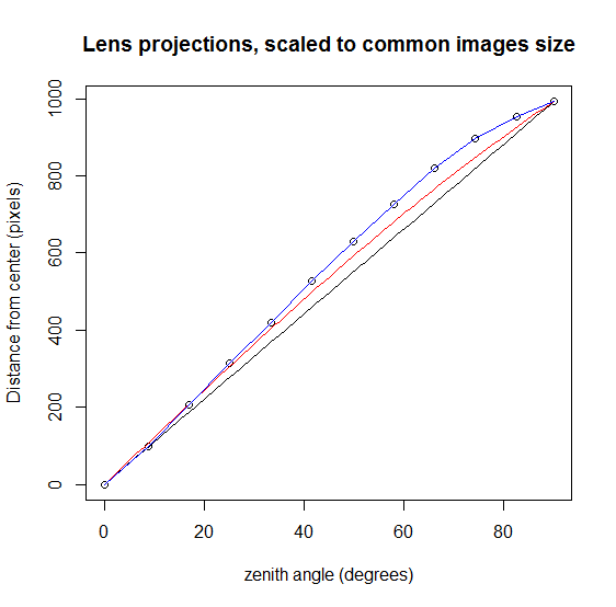
You can also calculate these values for other image projections to compare the distortion of your lens. Dividing the total pixels across by the total cells across gives the pixel count in each cell that would be expected from an equadistant angle projection. For equisolid projections, calculate the radial distance from the center by taking the sin of half the zenith angle in degrees and multiplying by the total pixel diameter divided by 180. I did this for a 180 degree Lensbaby GoPro attachment and plotted the actual pixel count for each viewing angle against equasolid and equidistant projections (see figure below). As you can see in the figure, for the Lensbaby lens, objects in the periphery of the frame are compressed (i.e. fewer pixels represent a given angle of view).
Downstream analysis applications can correct for lens distortion by weighting estimates from different radii in the image, but this means that errors are not continuous across the angle of view. In canopy measurements where the largest gaps will occur in the center of the image, this results in systematic bias of estimates.
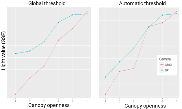
Although not a direct comparison of lenses, I took identical photos with a GoPro/Lensbaby system and a CanonDSLR/Sigma f2.8 system (equisolid) in locations with increasing canopy gaps. In more closed canopies, the lens distortion of the Lensbaby lens systematically overestimates light values (see figure below), even when using an automatic thresholding algorithm (we’ll go into all of this analysis in post 4).
Camera:
Which camera should you use? In theory, any camera with a 180 degree lens can be used for canopy estimates. But for accurate and replicable measurements, a camera with a high quality sensor and fully-programmable settings is required.
Sensors:
High quality is not synonymous with ‘a bazillion megapixels.’ A camera’s sensor is actually an array of many tiny sensors packed together. When the camera takes a photo, light enters through the lens and “collects” on each individual sensor, kind of like rain falling on a field collecting in an array of buckets. If we want to collect as much light (or rainwater) as possible, we want the largest sensor area (or bucket area) as possible. To use the rain-catching analogy, it won’t matter if we put out a bunch of tiny buckets or fewer large buckets, we’ll still collect the same amount of water if we cover the same area. The same goes for light. One can pack lots of pixels onto a tiny sensor, but at the end of the day, a bigger sensor will (pretty much) always produce higher quality image information, even if the total megapixel count is lower.
Camera control:
As digital cameras have become more popular in general, camera manufacturers have develop more powerful on-board computers that can do most of the thinking for the user. This is helpful for selfies, but not as useful for accurate research wherein we need to carefully select the camera’s settings. For accurate photos, you should be able to independently set the shutter speed, aperture, ISO, and light metering mode, at the very least (I’ll go over these settings in the next post).
Camera type:
DSLRs (digital single-lens reflex cameras like Canon EOS series cameras), especially full-frame DSLRs, house large sensors and are ideal for canopy photos because they are fully programmable. The downside is that they are heavy, expensive, and rarely weatherproof. (There’s nothing more nerve-wracking than sinking off-balanced into pond muck trying to keep a couple thousand dollars-worth of camera hardware above the surface!). In contrast, a cellphone with a clip-on hemisperical lens is light, relatively cheap, and can be waterproofed, but the image quality is too low and the parameters for image capture are difficult or impossible to set. A middle-ground option could be a point-and-shoot cameras (like the Nikon Coolpix); the primary disadvantage being the lack of standardization in lenses.
Capture format:
A final consideration is that your camera should be able to capture RAW images. RAW file formats retain all information for each pixel. Most consumer cameras, on the other hand, utilize image compression formats (like JPEG) that reduces file size by averaging pixel values and reducing information complexity. For most canopy measurement purposes, the first step of processing is binary compression (which is basically just a radical compression scheme), so pre-analysis compression should have little to no effect. If, however, one intends to spot-edit photos prior to processing (for instance applying exposure corrections to sun spots) RAW format will be required.
My setup:
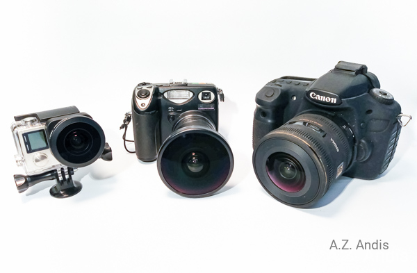
I’ve tried may camera systems and in the end, I think that a DSLR with a hemi-lens is really the best option if it is in your budget. I use a Canon 60D with the Sigma 4.5mm f2.8. You could also use a lower-end Canon (like a T-series Rebel) or Nikon camera body with the same lens. This setup offers a large sensor, full control over capture settings, and is well represented in the literature.
Stabilization
Finally, canopy photos require the camera to be pointed directly upward and perfectly level. The simplest option to achieve this orientation is to mount the camera to a tripod with a fully articulated head. A dual-axis bubble level placed on the lens cover should facilitate a perfectly level lens orientation.
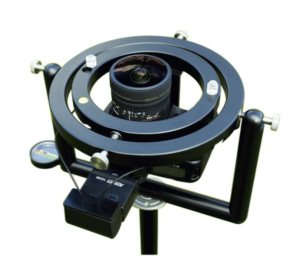
Repositioning and leveling a tripod for multiple sites gets very tedious, very quickly. To speed up the process, an auto-leveling device can be attached to the tripod. Once calibrated to the weight and balance of the camera, these devices ensure that the lens points opposite of gravity (i.e. level) at all times. Unfortunately, I’ve only seen these devices offered along with (expensive) proprietary software like HemiView, and the units are a bit heavy.
For most terrestrial applications, a tripod system will work well. However, if you need to take many photos at different points, a tripod is a pain to redeploy. Or, if you need photos over water (as in my case) tripods may be infeasible. To overcome this problem, I created a handheld stabilizer from a cheap steadycam (a free-rotating, dual-axis handle attached to a post with the camera mounted to the top and counterweights at the bottom) and an L-bracket (see the SECOND video in the IG post below). This rig allows me to move freely to sampling points and immediately take photos without an arduous setup process, while still ensuring that the lens is perfectly level.
In the next post, I cover how to take hemispherical canopy photos in the field, including sampling strategies and camera settings.
Be sure to check out my other posts about canopy research that cover the theory, hardware, field sampling, and analysis pipelines for hemispherical photos.
Also, check out my new method of canopy photography with smartphones and my tips for taking spherical panoramas.
References:
Fleck, M. M. (1994). Perspective Projection: the Wrong Imaging Model. Computer Science, University of Iowa.
Herbert, T. J. (1987). Area projections of fisheye photographic lenses. Agric. For. Meteorol. 39, 215–223. doi:10.1016/0168-1923(87)90039-6.
Rich, P. M. (1989). A Manual for Analysis of Hemispherical Canopy Photography. Los Alamos National Laboratory.